
    Saudi Arabia reference · GeoGiza review guide

    Traverse specifications in Saudi Arabia

    Read the specification, formula and evidence; choose your project grade to calculate.

    Specifications and error limits

    Deviation of one angle reading from its mean, not polygon angular-sum misclosure.

    Limits by work grade. Calculate using the grade named in your project.

    • local accuracy <2 mm

      max |vᵢ − mean(v)| ≤ 5″

      GEOSA · Land · V1.0

    • local accuracy <10 mm

      max |vᵢ − mean(v)| ≤ 10″

      GEOSA · Land · V1.0

    • local accuracy <30 mm

      max |vᵢ − mean(v)| ≤ 20″

      GEOSA · Land · V1.0

    Offsets for repeated readings of one angle in arcseconds after face reduction. The category name does not establish point-position acceptance.

    Documented editions; currentness and project applicability need confirmation.

    I do not know the required grade

    Check the contract, quality plan and receiving authority. An unspecified grade leaves project acceptance unresolved; browse and compare limits without an automatically chosen grade.

    Calculate the limit for your work

    All rules and evidence
    Rule, formula and evidence register for this task (5)

    All rules and evidence are available without JavaScript. Read the complete provision and project conditions.

    GEOSA Land · local accuracy <2 mm · angle deviation

    max |vᵢ − mean(v)| ≤ 5″

    Offsets for repeated readings of one angle in arcseconds after face reduction. The category name does not establish point-position acceptance.

    Conventional observations for the chosen local-accuracy category; consult Tables 12–13 for instruments, rounds and calibration.

    Technical Guidelines for Land Surveying

    General Authority for Survey and Geospatial Information · V1.0 · copyright 2025 · publication date not stated

    2.6.3.1.2 · Table 13 · printed 73 · PDF 73

    Copyable official address; direct linking requires publisher permission.

    https://geoportal.geosa.gov.sa/Geoportal/pdf/Land%20Survey%20Technical%20Guideline.pdf#page=73

    Edition/provision checked: 2026-10-12 · Currentness and project applicability need confirmation.

    Technical Guidelines for Land Surveying

    General Authority for Survey and Geospatial Information · V1.0 · copyright 2025 · publication date not stated

    2.6.3.1.1 · Table 12 · printed 72 · PDF 72

    Copyable official address; direct linking requires publisher permission.

    https://geoportal.geosa.gov.sa/Geoportal/pdf/Land%20Survey%20Technical%20Guideline.pdf#page=72

    Edition/provision checked: 2026-10-12 · Currentness and project applicability need confirmation.

    GEOSA Land · local accuracy <10 mm · angle deviation

    max |vᵢ − mean(v)| ≤ 10″

    Offsets for repeated readings of one angle in arcseconds after face reduction. The category name does not establish point-position acceptance.

    Conventional observations for the chosen local-accuracy category; consult Tables 12–13 for instruments, rounds and calibration.

    Technical Guidelines for Land Surveying

    General Authority for Survey and Geospatial Information · V1.0 · copyright 2025 · publication date not stated

    2.6.3.1.2 · Table 13 · printed 73 · PDF 73

    Copyable official address; direct linking requires publisher permission.

    https://geoportal.geosa.gov.sa/Geoportal/pdf/Land%20Survey%20Technical%20Guideline.pdf#page=73

    Edition/provision checked: 2026-10-12 · Currentness and project applicability need confirmation.

    Technical Guidelines for Land Surveying

    General Authority for Survey and Geospatial Information · V1.0 · copyright 2025 · publication date not stated

    2.6.3.1.1 · Table 12 · printed 72 · PDF 72

    Copyable official address; direct linking requires publisher permission.

    https://geoportal.geosa.gov.sa/Geoportal/pdf/Land%20Survey%20Technical%20Guideline.pdf#page=72

    Edition/provision checked: 2026-10-12 · Currentness and project applicability need confirmation.

    GEOSA Land · local accuracy <30 mm · angle deviation

    max |vᵢ − mean(v)| ≤ 20″

    Offsets for repeated readings of one angle in arcseconds after face reduction. The category name does not establish point-position acceptance.

    Conventional observations for the chosen local-accuracy category; consult Tables 12–13 for instruments, rounds and calibration.

    Technical Guidelines for Land Surveying

    General Authority for Survey and Geospatial Information · V1.0 · copyright 2025 · publication date not stated

    2.6.3.1.2 · Table 13 · printed 73 · PDF 73

    Copyable official address; direct linking requires publisher permission.

    https://geoportal.geosa.gov.sa/Geoportal/pdf/Land%20Survey%20Technical%20Guideline.pdf#page=73

    Edition/provision checked: 2026-10-12 · Currentness and project applicability need confirmation.

    Technical Guidelines for Land Surveying

    General Authority for Survey and Geospatial Information · V1.0 · copyright 2025 · publication date not stated

    2.6.3.1.1 · Table 12 · printed 72 · PDF 72

    Copyable official address; direct linking requires publisher permission.

    https://geoportal.geosa.gov.sa/Geoportal/pdf/Land%20Survey%20Technical%20Guideline.pdf#page=72

    Edition/provision checked: 2026-10-12 · Currentness and project applicability need confirmation.

    GEOSA Land · 20 mm horizontal classification at 95%

    U95(H) ≤ 20 mm

    From a processing/adjustment report: horizontal 95% confidence radius and, when required, ellipsoidal-height uncertainty at 95%. Alternatively derive them from 1σ ellipse axes and σh obtained from the full posterior variance matrix.

    Local or network horizontal control accuracy as identified by the adjustment report. Keep them distinct; this is not a line-misclosure or instrument-accuracy limit.

    Technical Guidelines for Land Surveying

    General Authority for Survey and Geospatial Information · V1.0 · copyright 2025 · publication date not stated

    2.2.4.1–2.2.4.2 · Table 2 · printed 14 · PDF 14

    Copyable official address; direct linking requires publisher permission.

    https://geoportal.geosa.gov.sa/Geoportal/pdf/Land%20Survey%20Technical%20Guideline.pdf#page=14

    Edition/provision checked: 2026-10-12 · Currentness and project applicability need confirmation.

    GEOSA Land · 50 mm horizontal classification at 95%

    U95(H) ≤ 50 mm

    From a processing/adjustment report: horizontal 95% confidence radius and, when required, ellipsoidal-height uncertainty at 95%. Alternatively derive them from 1σ ellipse axes and σh obtained from the full posterior variance matrix.

    Local or network horizontal control accuracy as identified by the adjustment report. Keep them distinct; this is not a line-misclosure or instrument-accuracy limit.

    Technical Guidelines for Land Surveying

    General Authority for Survey and Geospatial Information · V1.0 · copyright 2025 · publication date not stated

    2.2.4.1–2.2.4.2 · Table 2 · printed 14 · PDF 14

    Copyable official address; direct linking requires publisher permission.

    https://geoportal.geosa.gov.sa/Geoportal/pdf/Land%20Survey%20Technical%20Guideline.pdf#page=14

    Edition/provision checked: 2026-10-12 · Currentness and project applicability need confirmation.

    When to use this guide

    Use this guide when reviewing a traverse or planning conventional-network observations. Establish start/end points and reference orientation, then test measurement traceability before assessing adjusted coordinates.

    Closure and Bowditch corrections support arithmetic review, but alone do not establish acceptance of a SANSRS-tied network. Where the Geodesy guide applies, consult its adjustment and testing provisions rather than assuming any adjustment method is interchangeable.

    The checklists and examples are original GeoGiza guidance, not specification text, a translation or a compliance certificate. Consult the original document and project scope for applicable grades and mandatory limits.

    Edition verified; currentness unconfirmed

    Publisher, V1.0, copyright 2025 and page locators were checked on 11 October 2026. The copyright year is not a verified publication date. Currentness and any superseding update remain unconfirmed; check with GEOSA, the receiving authority and the project contract before adopting requirements.

    What to prepare before review

    • Control coordinates, provenance, frame, epoch and starting orientation.
    • Raw angles/distances, units and ordered traverse legs.
    • Instrument/prism heights, centering/calibration checks and repeat logs.
    • Network class, processing method, tests and receiving-authority requirements.

    Practical review steps

    1. 1

      Establish the control connection

      Match point identifiers to descriptions and coordinate provenance. Record project frame, projection, zone and epoch; an older-datum point does not become KSA-GRF17 by renaming the file.

    2. 2

      Inspect observations before closure

      Use the existing traverse template for structured inspection; check units, orientations, station sequence and repeats. Preserve the raw version when correcting an entry.

    3. 3

      Select processing for the commissioned task

      Compute raw closure with the tool, then request adjustment appropriate to the network class. For precise control, document weights, residuals and required tests; distributing closure does not reveal every systematic error.

    4. 4

      Tie the decision to a reproducible review file

      Retain control, observations, raw calculations, adjustment report, software versions and issues. Assign an action and owner to each reservation; a tidy adjusted result does not establish network quality.

    Understand the concept visually
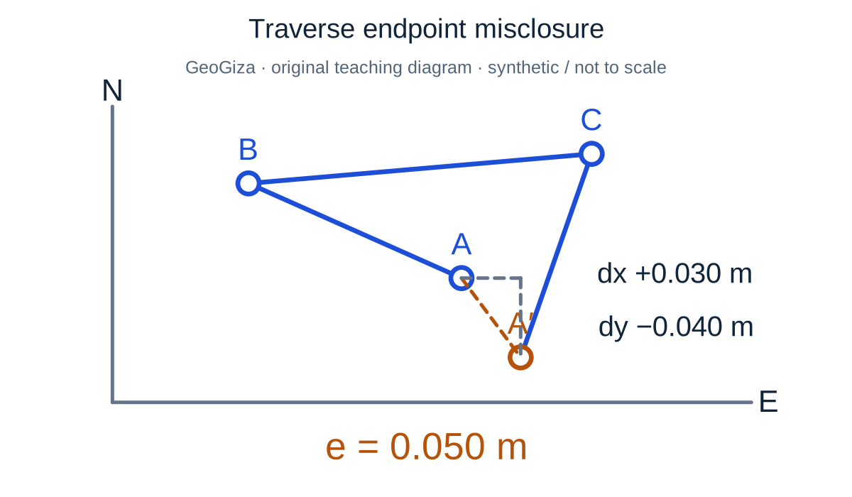
    Traverse endpoint misclosure

    Original GeoGiza teaching diagram · synthetic data · not acceptance limits or official approval

    Traverse endpoint misclosure

    Endpoint difference means calculated minus reference. In this teaching example dx = +0.030 m and dy = −0.040 m, giving a 0.050 m misclosure. The difference vector is enlarged for visibility.

    e = √(dx² + dy²) = 0.050 m; cEᵢ = −dx × Lᵢ / ΣL; cNᵢ = −dy × Lᵢ / ΣL

    Misclosure describes a difference; acceptance requires the applicable reference, work grade and observation checks.

    cEᵢ and cNᵢ correct the east/north components of each traverse leg; Lᵢ is its length and ΣL the total leg length. Bowditch corrections oppose the misclosure and are proportional to line lengths; distributing them does not prove control-network quality. Not to scale.

    Consult this topic’s document locators

    SYNTHETIC teaching example — not field observations or a tolerance limit

    Synthetic example: small closure, missing evidence

    A synthetic traverse has coordinate differences of 0.012 m east and 0.016 m north, a magnitude of 0.020 m. Only adjusted coordinates are supplied; observation weights and control provenance are missing.

    What to record in the review

    Record the arithmetic difference and request raw observations, ties and processing evidence before deciding. The example’s 20 mm is neither a Saudi acceptance limit nor proof of network quality.

    Mistakes affecting the review decision

    • Importing a tolerance from a different commission or country.
    • Adjusting a SANSRS network arithmetically without appropriate reports/tests.
    • Removing discrepant observations without an exclusion record.

    Official sources and reading locators

    Printed and PDF page numbers match in these copies. Source addresses are copyable under the publisher’s linking terms; consult the complete provision in the edition applicable to your project.

    General Authority for Survey and Geospatial Information (GEOSA) · Technical reference

    Technical Guidelines for Land Surveying

    V1.0 · copyright 2025 · publication date not stated

    Locator:
    2.2.5.2–2.2.5.3 — conventional control
    Printed pages:
    19
    PDF viewer pages:
    19

    Publisher document address — copy into your browser:

    https://geoportal.geosa.gov.sa/Geoportal/pdf/Land%20Survey%20Technical%20Guideline.pdf#page=19

    General Authority for Survey and Geospatial Information (GEOSA) · Technical reference

    Technical Guidelines for Land Surveying

    V1.0 · copyright 2025 · publication date not stated

    Locator:
    2.6.3.1.2 — traverse observations
    Printed pages:
    73
    PDF viewer pages:
    73

    Publisher document address — copy into your browser:

    https://geoportal.geosa.gov.sa/Geoportal/pdf/Land%20Survey%20Technical%20Guideline.pdf#page=73

    General Authority for Survey and Geospatial Information (GEOSA) · Technical reference

    Technical Guidelines for Geodesy

    V1.0 · copyright 2025 · publication date not stated

    Locator:
    2.7 — control-network adjustment
    Printed pages:
    53–54
    PDF viewer pages:
    53–54

    Publisher document address — copy into your browser:

    https://geoportal.geosa.gov.sa/Geoportal/pdf/Geodesy%20Technical%20Guideline.pdf#page=53

    Source checked:

    Source methodology and copyright

    Frequently asked questions

    Does Bowditch establish Saudi control-network compliance?

    No. It is an arithmetic distribution method in the existing tool. Establish network scope and processing/testing requirements from the reference and commission; it does not replace required adjustment and validation.

    Do I need a new Saudi traverse template?

    The existing generic template organizes observations. Attach control provenance, epoch, processing report and project requirements; the template is not a GEOSA approval form.