

The drawing is a promise — the as-built is the receipt
A set of construction drawings is a statement of intent: this column centre at this coordinate, this slab at this level, these anchor bolts on this grid. Concrete, steel, and human hands rarely hit intent exactly. Formwork shifts under load, a bolt template walks a few millimetres, a slab cures with a fall the design never asked for. An as-built survey is how we record where the structure actually ended up — and the difference between the drawing and the receipt is the entire reason the survey exists.
On our construction projects the question is almost never 'is the building roughly right?' — by eye, nearly everything looks fine. The real question is whether each defined feature lands inside its stated tolerance, and where it does not, by how much and in which direction. That turns 'looks fine' into a documented, coordinate-true claim the structural engineer can sign against. We measure the truth; the design authority decides what to do with it.
From real construction sites, not a spec sheet
- 90
- instruments in the fleet
- total stations, scanners, GNSS, levels
- 1,000+
- survey projects delivered
- 2,500+
- clients served
Two instruments, two kinds of truth
An as-built is not one method. The total station measures the things you can name: column centres, slab edges, steel-connection nodes, anchor-bolt patterns, level points. You point at a defined feature and get its coordinate to millimetre relative precision — perfect when you already know exactly what must be checked against the drawing.
The laser scanner works the opposite way. Instead of choosing points, it records everything in line of sight as a dense point cloud — millions of measured points per setup. That is what you want in a congested plant room, a façade, an MEP riser, or a heritage interior, where the clash you need to find is the one nobody thought to measure. The catch is that a scan floats in its own space until you tie it to the project control — which is exactly the job the total station does first.
Total station vs laser scanner for as-built work
| Criterion | Total station | Laser scanner |
|---|---|---|
| Captures | Chosen, defined points | Everything in view (point cloud) |
| Typical relative accuracy | ±2–5 mm | ±2–6 mm at range |
| Best for | Grids, levels, anchor bolts | Congestion, surfaces, clash, heritage |
| Data volume to process | Light | Heavy (point cloud) |
| Ties to project control | Directly | Via control / targets |
| Time on a complex space | Slow, point by point | Fast, whole-room |
Neither replaces the other. The highlighted column is the better fit for that row; on big jobs we run both together.
How we run an as-built survey
- 1
Tie to control: re-occupy the project control network with the total station so every later measurement and scan shares the same coordinate frame as the original design.
- 2
Agree the tolerance: pull the allowed deviation band for each feature from the structural spec or the relevant code, so 'pass' and 'fail' are defined before anyone measures.
- 3
Measure defined features: with the total station, capture column centres, slab levels, anchor bolts, and connection nodes — the points that carry a named tolerance.
- 4
Scan the congestion: with the laser scanner, capture complex or clash-prone areas as a registered point cloud, tying each setup to control targets.
- 5
Compute deviations: subtract design from measured for every feature and surface, then colour-map the result so direction and magnitude are visible at a glance.
- 6
Flag and deliver: highlight every point outside tolerance with its coordinate and magnitude, register the scan to a scan-to-BIM (IFC) model, and hand the structural engineer a record they can act on.
A deviation only means something against a tolerance
The single most common mistake we see in as-built reporting is a number with no band around it. 'The column is 7 mm off' is not a finding — it is an anecdote. Off from what, and is 7 mm allowed? An as-built becomes useful the moment every measured-minus-design value is judged against a stated tolerance agreed up front, usually pulled straight from the structural specification or the governing code.
So we colour-map it. Across the whole structure, every checked feature is shaded by how far it sits from design: inside the band it is recorded and passes; outside it, it is flagged with its coordinate, its magnitude, and its direction so the engineer can rule on accept, rework, or a documented concession. We never adjudicate the structure — we hand the design authority an honest, complete picture and let them decide.
A worked tolerance check (illustrative)
| Feature | Design value | Measured | Deviation | Allowed band | Status |
|---|---|---|---|---|---|
| Column C-12 centre (E) | 100.000 m | 100.004 m | +4 mm | ±10 mm | Pass |
| Column C-12 centre (N) | 250.000 m | 249.991 m | -9 mm | ±10 mm | Pass |
| Slab level, grid B/3 | +14.500 m | +14.481 m | -19 mm | ±15 mm | Flag — review |
| Anchor-bolt group AB-7 | as drawn | +6 mm spread | +6 mm | ±5 mm | Flag — review |
| Steel node SN-3 | as drawn | +2 mm | +2 mm | ±8 mm | Pass |
A finding is a measurement plus a tolerance plus a status — never a bare millimetre. · Coordinates and tolerances are illustrative; actual allowed bands are taken from the project structural specification or governing code per job.
Typical relative accuracy by as-built method
An out-of-adjustment instrument fails a good structure
Before an as-built, our total stations and scanners are field-checked against ISO 17123 procedures and the work is tied back to verified project control. The reason is blunt: an instrument that is a few seconds out of collimation, or a scan that is poorly registered, will report deviations that are not real — failing a structure that was actually built correctly, or passing one that was not. The tolerance check is only honest if the instrument behind it is provably in adjustment.
From raw scan to coordinate-true model
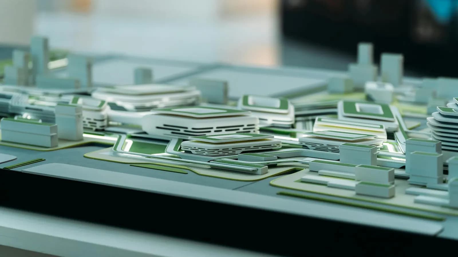 Scan-to-BIM model
 Raw point cloud
Drag to compare: the registered point cloud becomes an IFC model the whole project team can query against the design.
The instruments behind the verification
 From our field work
Total stations
Survey instruments for precise angle and distance measurement — control networks, layout, and as-builts.
such as Leica TS16, Viva TS, Topcon ES-series

Laser scanners
Terrestrial 3D laser scanning that captures dense point clouds for scan-to-BIM and as-builts.
such as Leica RTC360, FARO Focus
Representative classes from the GeoGiza fleet. Photographs are illustrative of each instrument class.
Take the as-built further
References
- ISO 17123 series — Field procedures for testing geodetic and surveying instruments — International Organization for Standardization (ISO)
- IFC open standard for Building Information Modeling (BIM) and scan-to-BIM delivery — buildingSMART International