What a topographic survey actually delivers
A topographic survey answers one question with measurable certainty: where is everything, and how high is it? Not roughly — to a stated accuracy, in a stated coordinate frame, layered cleanly enough that a road designer, a drainage engineer, or an architect can build straight on top of it. The romantic image is a surveyor with a telescope. The real work is a disciplined chain: set the frame, capture the ground, then turn raw observations into a contoured CAD surface that holds up under scrutiny. Below is how our crews run that chain, end to end, on a real site.
The ground under our methods
- 90
- instruments in the fleet
- total stations, GNSS, levels, scanners, drones, sonar
- 1,000+
- survey projects delivered
- 800,000+
- feddans levelled
- where contour accuracy is the whole job
Step 1 — Control comes first, always
Before anyone shoots a ground point, we build the frame everything else hangs from: a small control network of marked, permanent-enough points whose coordinates we know to high confidence and that are tied to the national grid. This is the unglamorous part that decides whether the whole survey is worth anything. Get it right and every RTK shot and every total-station observation lands in one consistent datum and projection; get it wrong and you produce a thousand points that each look fine and don't agree with each other.
We declare the datum and projection up front — the EPSG code is part of the deliverable, not an afterthought — so the client's GIS or design team isn't guessing what frame the numbers live in. On most jobs the control itself is a hybrid: a GNSS static or fast-static session to fix a couple of base points hard to the grid, then those carried through the site so the rest of the day's work inherits them.
Step 2 — Capture the ground: RTK in the open, total station in the shadows
With control set, capture is a division of labour by line-of-sight. Out in the open — fields, car parks, bare terrain — GNSS-RTK is fast: walk the detail, tag each point with a feature code, and the position drops straight onto the grid. But RTK needs sky, and real sites have canopy, walls, narrow alleys, and the inside of buildings. There the total station takes over, traversing in from known control and measuring angles and distances to a prism with a precision satellites can't reach under cover. Same frame, two instruments, no seams. The discipline that makes the office work possible is coding: top vs toe of bank, edge of pavement, kerb line, the breaklines that tell the software where the ground changes slope. Points without codes are just confetti.
Field-to-CAD: the end-to-end method
- 1
Recon and plan: walk the site, identify what must be captured, plan control placement and access.
- 2
Establish control: fix base points to the national grid (GNSS static/fast-static), declare datum + EPSG projection.
- 3
RTK ground capture: collect coded detail points and breaklines across all open, sky-visible ground.
- 4
Total-station fill: traverse from control into canopy, alongside structures, and indoors where RTK can't see sky.
- 5
Field QA: check shots against known control, re-observe outliers, confirm point density is sufficient before leaving site.
- 6
Download and reduce: import raw observations, apply the coordinate frame, clean and verify the point cloud of survey points.
- 7
Build the surface: triangulate points with breaklines into a terrain model and generate contours.
- 8
Produce the CAD deliverable: layer points, planimetry, breaklines and contours into a DWG on the stated datum/projection.
- 9
Final QA and handover: validate contours against spot levels, confirm layering/projection, issue the DWG plus point list.
Which instrument leads, where
| Site condition | GNSS-RTK | Total station |
|---|---|---|
| Open ground, clear sky | Fast, grid-direct | Slower, needs intervisibility |
| Under canopy / beside tall walls | Loses sky, unreliable | Works on line of sight |
| Indoors / under structures | No fix | Yes |
| Tight relative precision (layout, monitoring) | ±15–25 mm typical | ±2–5 mm typical |
| Tie to national grid | Direct, instant | Carried from control |
On a real site we use both: RTK sets and covers the open ground, the total station fills every shadow it can't reach. Typical/illustrative accuracies — see chart source note.
Typical positional accuracy by capture method
Per ISO 17123 and NGS RTK practice
We field-test instruments to ISO 17123 before deployment, so the accuracy we quote is the accuracy the instrument can actually hold — calibration drift is caught on the test, not on your site. RTK observations follow established good practice (NGS RTK guidance): adequate occupation time, redundant checks against known control, and fixed-not-float solutions only. And every deliverable states its datum and projection by EPSG code, so the coordinates are unambiguous in any GIS.
From raw terrain to a measurable surface
 Contour map
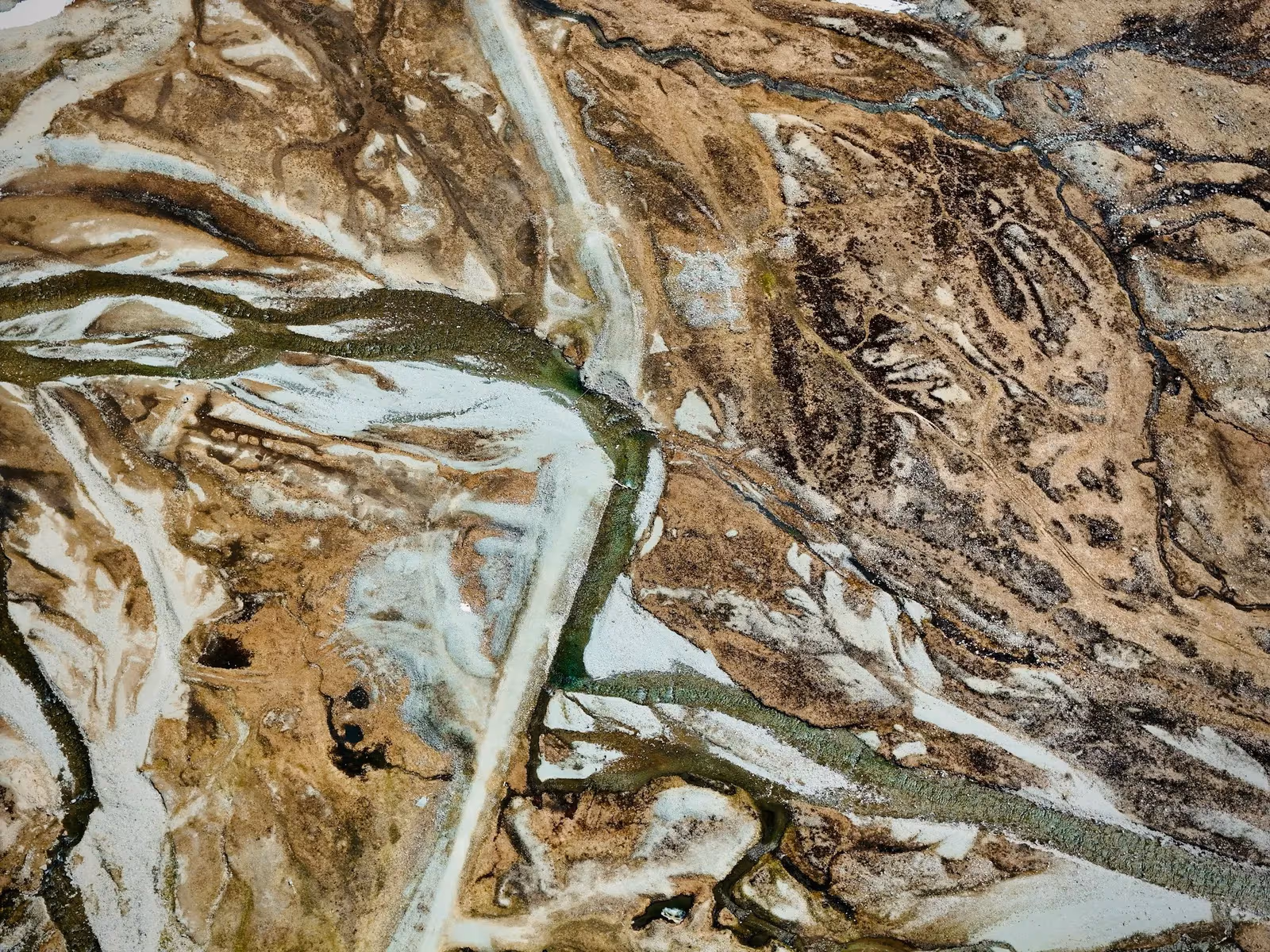 Raw terrain
Drag to compare. The coded field points and breaklines triangulate into a surface; the surface generates the contours a designer can build on.
Step 3 — Processing: from observations to a DWG that holds up
Back in the office the points become a surface. We import the raw observations, apply the declared coordinate frame, and clean: throw out the obvious blunders, re-check any shot that disagrees with a known control point, and confirm the density is enough to describe the ground honestly. Then the codes earn their keep — the software triangulates the points with the breaklines, so contours bend along the top of a bank or the edge of a road instead of smearing across them. Contours generated without breaklines are the classic giveaway of a survey done in a hurry.
The output is not 'the points'. It's a layered DWG: surveyed points on their layer, planimetric detail on theirs, breaklines and contours on theirs, all on the stated datum and EPSG projection, with the point list alongside. Where the project needs it we also issue the surface model itself. The test we hold it to is simple — can a designer open this and start work without re-surveying anything? If yes, the job is done.
The instruments behind the capture
 From our field work
Total stations
Survey instruments for precise angle and distance measurement — control networks, layout, and as-builts.
such as Leica TS16, Viva TS, Topcon ES-series
 From our field work
GPS / GNSS / RTK receivers
Survey-grade GPS receivers for centimeter-accurate satellite positioning (RTK) — control, topographic, and cadastral work.
such as Trimble R10/R8, Topcon Hiper V, Leica GS18
Representative classes from the GeoGiza fleet of 90 instruments — total stations and GNSS receivers. Photographs are illustrative of each class.
Take it further
References
- Guidelines for Real-Time Kinematic (RTK) GNSS surveying and geodetic control — US National Geodetic Survey (NGS/NOAA)
- ISO 17123 series — Field procedures for testing geodetic and surveying instruments — International Organization for Standardization (ISO)
- EPSG registry of coordinate reference systems and map projections — EPSG Geodetic Parameter Dataset